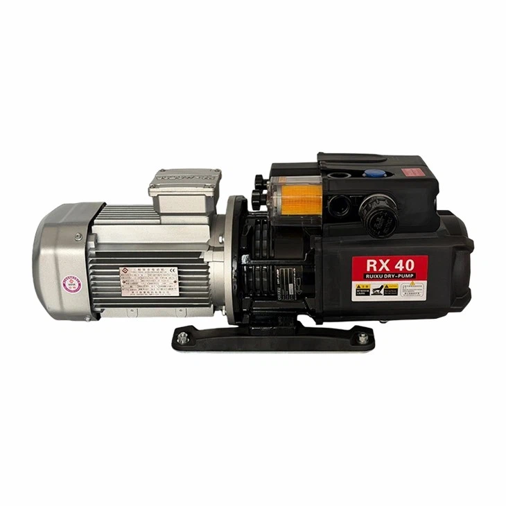
Overall Structural Configuration of the Pump
The arrangement of the vacuum pump's body structure determines the pump's overall configuration.
In the vertical configuration, the inlet and exhaust ports are positioned horizontally, making assembly and pipeline connections relatively convenient. However, the pump's center of gravity is high, resulting in poor stability during high-speed operation; consequently, this configuration is predominantly used for small-scale pumps.
In the horizontal pump configuration, the inlet port is located at the top, while the exhaust port is at the bottom. Occasionally-to facilitate the installation and connection of vacuum system piping-the exhaust port may be routed horizontally; in this arrangement, the directions of the inlet and exhaust flows are mutually perpendicular. In such cases, the exhaust port can be opened on either the left or the right side; one end connects to the exhaust piping, while the other end is either capped off or fitted with a bypass valve. This pump structure features a low center of gravity, ensuring excellent stability during high-speed operation. Generally, this structural configuration is widely adopted for medium-to-large-scale pumps.
In another configuration, the axes of the pump's two rotors are mounted perpendicular to the horizontal plane. This structure facilitates easy control of assembly clearances and convenient rotor installation, while also minimizing the pump's footprint. However, the pump's center of gravity remains relatively high, the removal and installation of gears can be cumbersome, and the lubrication mechanism is comparatively complex.
Pump Transmission Methods
The two rotors of the vacuum pump achieve synchronized relative motion through a pair of high-precision gears. The drive shaft is coupled to the electric motor via a mechanical coupling. Regarding the layout of the transmission structure, two primary configurations exist: The first involves positioning both the electric motor and the gears on the same side of the rotors. In this arrangement, the driven rotor is driven directly by the gears located at the motor end of the assembly. Consequently, torsional deformation of the drive rotor shaft is minimized; this ensures that the clearance between the two rotors remains unaffected by excessive torsional strain on the drive shaft, thereby maintaining a uniform clearance between the rotors throughout the operational cycle. The primary disadvantages of this transmission method are: The drive shaft requires three bearings, which increases the complexity of the pump's machining and assembly processes, while also making the removal, installation, and adjustment of the gears more difficult; and The overall structural configuration is asymmetrical, causing the pump's center of gravity to shift toward the side housing the electric motor and gearbox.